
This is an old revision of the document!
Table of Contents
Building a bike model
Overview
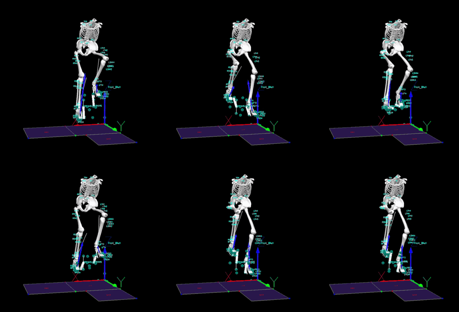
This tutorial outlines the process to build a model for a bike pedal and crank and how to assign force data from analog signals. This tutorial assumes your human model is already built. Follow this tutorial to create a model before continuing Building 6DOF Model. This tutorial will have two parts, the first part will show how to create the model for the bike pedal and crank, and the second will show the force data processing. Full completed CMZ can be downloaded here: Bike Model CMZ Complete. The final CMZ should resemble the following noting the moving forces on the feet from the pedals.
Model Building
Building this model is very tedious as there are a lot landmarks and segments required. It is important to follow the order outlined below as certain landmarks and segments are build off previously defined items. To create a new landmark click on the Landmarks tab, select Add New Landmark, input the definitions below and press Apply.


To build a new segment select the Segment tab input your desired segment name, ensure the segment type is Visual 3D, select Create, input the definitions for the segments shown below, and select Apply.


The first set of landmarks define a virtual position for the cranks
| Landmark | Starting Point | Existing Coordinate System | ML Offset | AP Offset | AXIAL Offset |
| VRCRKAXIS | RCRKAXIS | LAB | -0.0045 | 0 | 0 |
| VLCRKAXIS | LCRKAXIS | LAB | 0.0045 | 0 | 0 |
The following set of landmarks define virtual positions from the pedal markers in the LAB
| Landmark | Starting Point | Existing Coordinate System | ML Offset | AP Offset | AXIAL Offset |
| VRPED1_X | RPED1 | LAB | -0.3 | 0 | 0 |
| VRPED1 | RPED1 | LAB | -0.6 | 0 | 0 |
| VRPED2 | RPED2 | LAB | -0.3 | 0 | 0 |
| VRPED3 | RPED3 | LAB | -0.5 | 0 | 0 |
| VLPED1_X | LPED1 | LAB | 0.3 | 0 | 0 |
| VLPED1 | LPED1 | LAB | 0.6 | 0 | 0 |
| VLPED2 | LPED2 | LAB | 0.3 | 0 | 0 |
| VLPED3 | LPED3 | LAB | 0.5 | 0 | 0 |
| VRPED3_0 | RPED3 | LAB | -0.2 | 0 | 0 |
| VLPED3_0 | LPED1 | LAB | 0.2 | 0 | 0 |
| VRPED2_X1 | RPED2 | LAB | -0.07 | 0 | 0 |
| Landmark | Starting Point | Ending Point | Project From |
| MRPED1 | RPED1 | VRPED1_X | VRCRKAXIS |
| MLPED1 | LPED1 | VLPED1_X | VLCRKAXIS |
The following set of landmarks are for the Bike Lab Coordinate systems.
| Landmark | Starting Point | Existing Coordinate System | ML Offset | AP Offset | AXIAL Offset |
| B_LAB_Z | LCRKAXIS | LAB | 0 | 0 | 0.1 |
| B_LAB_Y | LCRKAXIS | LAB | 0 | 0.1 | 0 |
| B_LAB_X | LCRKAXIS | LAB | 0.1 | 0 | 0 |
| B_LAB_Z_R | RCRKAXIS | LAB | 0 | 0 | 0.1 |
| B_LAB_Z_R | RCRKAXIS | LAB | 0 | 0.3 | 0 |
| B_LAB_Z_R | RCRKAXIS | LAB | 0.1 | 0 | 0 |
We can now define our first segments.
| Segment | Proximal Joint | Distal Joint | Extra Signal | Tracking Signals |
| Right Pedal 1 | Lateral: VRPED3_0 Radius:0.07 | lateral: RPED2 Radius:0.07 | Medial: RPENDANT | MRPED1, RPED2, RPED3 |
| Left Pedal 1 | Lateral: VLPED3_0 Radius:0.07 | lateral: LPED2 Radius:0.07 | Medial: LPENDANT | MLPED1, LPED2, LPED3 |
| Bike_Lab | Joint Center: B_LAB_Z Radius:0.07 | Joint center: LCRKAXIS Radius:0.01 | Anterior: B_LAB_Y | B_LAB_Z, B_LAB_Y, B_LAB_X, LCRKAXIS |
| R_Bike_Lab | Joint Center: B_LAB_Z_R Radius:0.07 | Joint center: RCRKAXIS Radius:0.01 | Anterior: B_LAB_Y_R | B_LAB_Z_R, B_LAB_Y_R, B_LAB_X_R, RCRKAXIS |
| AXIS | Joint Center: RCRKAXIS Radius:0.1 | Joint center: CRANK_Z Radius:0.01 | Medial: LCRKAXIS | Check Use Calibration signals for Tracking |
We can now define the next group of Landmarks built using the segments created above.
| Landmark | Starting Point | Existing Coordinate System | ML Offset | AP Offset | AXIAL Offset |
| VRPED1_Z | VRPED1 | Right Pedal 1 | 0 | 0.21 | 0 |
| VRPED2_Z | VRPED2 | Right Pedal 1 | 0 | 0.21 | 0 |
| VRPED3_Z | VRPED3 | Right Pedal 1 | 0 | 0.21 | 0 |
| VLPED1_Z | VLPED1 | Left Pedal 1 | 0 | 0.21 | 0 |
| VLPED1_Z | VLPED2 | Left Pedal 1 | 0 | 0.21 | 0 |
| VLPED1_Z | VLPED3 | Left Pedal 1 | 0 | 0.21 | 0 |
| MRPED1_Z | MRPED1 | Right Pedal 1 | 0 | 0.21 | 0 |
| MLPED1_Z | MLPED1 | Left Pedal 1 | 0 | 0.21 | 0 |
| VRPED1_Z_X | VRPED1_Z | Right Pedal 1 | -0.38 | 0 | 0 |
| VRPED2_Z_X | VRPED2_Z | Right Pedal 1 | -0.38 | 0 | 0 |
| VLPED1_Z_X | VLPED1_Z | Left Pedal 1 | -0.38 | 0 | 0 |
| VLPED2_Z_X | VLPED2_Z | Left Pedal 1 | -0.38 | 0 | 0 |
We now have all the required Landmarks to define the final 4 segments.
| Segment | Proximal Joint | Distal Joint | Extra Signal | Tracking Signals | |
| Right Pedal | Joint Center: VRPED1_Z_X Radius:0.038 | lateral: VRPED2_Z_X Radius:0.038 | Lateral: VRPED1 | MRPED1_Z, RPED2, RPED3 | 0.01 |
| Left Pedal | Joint Center: VLPED1_Z_X Radius:0.038 | lateral: VLPED2_Z_X Radius:0.038 | Lateral: VLPED1 | MLPED1_Z, LPED2, LPED3 | 0.01 |
| Right Crank | Joint Center: RCRKAXIS Radius:0.01 | lateral: MRPED1 Radius:0.01 | Lateral: RPED1 | MRPED1, RCRKAXIS, RPED1 | 0.01 |
| Left Crank | Joint Center: LCRKAXIS Radius:0.01 | lateral: MLPED1 Radius:0.01 | Lateral: LPED1 | MLPED1, LCRKAXIS, LPED1 | 0.01 |
You should now have all the landmarks and segments built for your model and you human and bike model should resemble the following.

Force Processing
Force data from bikes is often imported using analog signals not force plates. Data requires processing to interpret. The following steps will show the command pipeline used for this process. The completed pipeline can also be downloaded here. Not there are values specific to this data such as variable names and lever arms based on pedal size that will need to be changed based on the specific data.
The original force data is very noisy so a low-pass filter is used to smooth the data. The command Lowpass_Filter can be under Signal Filter press » to add to your pipeline.
Lowpass_Filter
/SIGNAL_TYPES= ANALOG
! /SIGNAL_FOLDER=ORIGINAL
! /SIGNAL_NAMES=
! /RESULT_FOLDER=PROCESSED
! /RESULT_SUFFIX=
! /FILTER_CLASS=BUTTERWORTH
 /FREQUENCY_CUTOFF=6.0
 /NUM_REFLECTED=6
! /NUM_EXTRAPOLATED=0
/TOTAL_BUFFER_SIZE=20
! /NUM_BIDIRECTIONAL_PASSES=1
;
Once smoothed the Evaluate_Expression command can be used to determine the Force in each pedal before using the Transform_Data_Coordinate_System to convert force values to the Lab.
Force
/Right
Evaluate_Expression
/EXPRESSION= VECTOR((-1.0*ANALOG::PROCESSED::Force.Fx_2),((1.0*ANALOG::PROCESSED::Force.Fy_3)+(1.0*ANALOG::PROCESSED::Force.Fy_4)),((1.0*ANALOG::PROCESSED::Force.Fz_3)+(1.0*ANALOG::PROCESSED::Force.Fz_4)))
/SIGNAL_TYPES=ANALOG
! /SIGNAL_FOLDER=PROCESSED
/SIGNAL_NAMES=Force.Fx_2+Force.Fy_3+Force.Fy_4+Force.Fz_3+Force.Fz_4
! /SIGNAL_COMPONENTS=
! /RESULT_TYPES=DERIVED
/RESULT_FOLDERS=FORCE_RIGHT
/RESULT_NAME= FORCE
! /APPLY_AS_SUFFIX_TO_SIGNAL_NAME=FALSE
;

Transform_Data_Coordinate_System
/SIGNAL_TYPES= DERIVED
/SIGNAL_FOLDER=FORCE_RIGHT
/SIGNAL_NAMES= FORCE
! /FROM_SEGMENT_CS= Right Pedal
/TO_SEGMENT_CS= LAB
/RESULT_TYPES= DERIVED
/RESULT_FOLDERS= FORCE_LAB_RIGHT
!/RESULT_NAME=
! /APPLY_AS_SUFFIX_TO_SIGNAL_NAME=TRUE
/ORIENTATION_ONLY=TRUE
! /USE_DATA_RATE=FALSE
;

============
/Left
============

Evaluate_Expression
/EXPRESSION= VECTOR((-1.0*ANALOG::PROCESSED::Force.Fx),((1.0*ANALOG::PROCESSED::Force.Fy)+(1.0*ANALOG::PROCESSED::Force.Fy_2),((1.0*ANALOG::PROCESSED::Force.Fz)+(1.0*ANALOG::PROCESSED::Force.Fz_2)))
/SIGNAL_TYPES=ANALOG
! /SIGNAL_FOLDER=PROCESSED
/SIGNAL_NAMES=Force.Fx+Force.Fy+Force.Fy_2+Force.Fz+Force.Fz_2
! /SIGNAL_COMPONENTS=
! /RESULT_TYPES=DERIVED
/RESULT_FOLDERS=FORCE_LEFT
/RESULT_NAME= FORCE
! /APPLY_AS_SUFFIX_TO_SIGNAL_NAME=FALSE
;

Transform_Data_Coordinate_System
/SIGNAL_TYPES= DERIVED
/SIGNAL_FOLDER=FORCE_LEFT
/SIGNAL_NAMES= FORCE
! /FROM_SEGMENT_CS= Left Pedal
/TO_SEGMENT_CS= LAB
/RESULT_TYPES= DERIVED
/RESULT_FOLDERS= FORCE_LAB_LEFT
!/RESULT_NAME=
! /APPLY_AS_SUFFIX_TO_SIGNAL_NAME=TRUE
/ORIENTATION_ONLY=TRUE
! /USE_DATA_RATE=FALSE
;
In order to change the force assignments the Center Of Pressure and Freemoment for each pedal are also required. First we must compute the moment, followed by the COP and finally the Freemoment.
Moment
Note that the decimal coefficients are lever arm measurements that will change based on pedal size.
============
/Right
============

Evaluate_Expression
/EXPRESSION=VECTOR((0.02845*DERIVED::FORCE_RIGHT::FORCE::Y),((0.01945*ANALOG::PROCESSED::Force.Fz_4-0.01945*ANALOG::PROCESSED::Force.Fz_3)-0.02845*ANALOG::PROCESSED::Force.FX_2),((0.01945*ANALOG::PROCESSED::Force.Fy_4-0.01945*ANALOG::PROCESSED::Force.Fy_3)))
/RESULT_NAME=MOMENT
/RESULT_TYPE=DERIVED
/RESULT_FOLDER=FORCE_RIGHT
;

============
/Left
============

Evaluate_Expression
/EXPRESSION=VECTOR((0.02845*DERIVED::FORCE_LEFT::FORCE::Y), ((-0.01945*ANALOG::PROCESSED::Force.Fz + 0.01945*ANALOG::PROCESSED::Force.Fz_2) - 0.02845*ANALOG::PROCESSED::Force.FX), ((0.01945*ANALOG::PROCESSED::Force.Fy - 0.01945*ANALOG::PROCESSED::Force.Fy_2)))
/RESULT_NAME=MOMENT
/RESULT_TYPE=DERIVED
/RESULT_FOLDER=FORCE_LEFT
;
Center Of Pressure
============
/Right
============

Evaluate_Expression
/EXPRESSION=VECTOR((-1 * DERIVED::FORCE_RIGHT::MOMENT::Y / DERIVED::FORCE_RIGHT::FORCE::Z), (DERIVED::FORCE_RIGHT::MOMENT::X / DERIVED::FORCE_RIGHT::FORCE::Z), (0.0*analog::processed::Force.Fx_2))
/RESULT_NAME=COP
 /RESULT_TYPE=DERIVED
 /RESULT_FOLDER=FORCE_RIGHT
;

Transform_Data_Coordinate_System
/SIGNAL_TYPES=DERIVED
/SIGNAL_NAMES=COP
/SIGNAL_FOLDER=FORCE_RIGHT
/FROM_SEGMENT_CS=Right Pedal
/TO_SEGMENT_CS=Lab
/RESULT_TYPE=Derived
/RESULT_FOLDER=FORCE_LAB_RIGHT
/RESULT_SUFFIX=
/ORIENTATION_ONLY=FALSE
! /USE_DATA_RATE=FALSE
;

============
/Left
============

Evaluate_Expression
/EXPRESSION=VECTOR((-1*DERIVED::FORCE_LEFT::MOMENT::Y / DERIVED::FORCE_LEFT::FORCE::Z), (DERIVED::FORCE_LEFT::MOMENT::X / DERIVED::FORCE_LEFT::FORCE::Z), (0.0*analog::processed::Force.Fx))
/RESULT_NAME=COP
 /RESULT_TYPE=DERIVED
 /RESULT_FOLDER=FORCE_LEFT
;

Transform_Data_Coordinate_System
/SIGNAL_TYPES=DERIVED
/SIGNAL_NAMES=COP
/SIGNAL_FOLDER=FORCE_LEFT
/FROM_SEGMENT_CS=Left Pedal
/TO_SEGMENT_CS=Lab
/RESULT_TYPE=Derived
/RESULT_FOLDER=FORCE_LAB_LEFT
/RESULT_SUFFIX=
/ORIENTATION_ONLY=FALSE
! /USE_DATA_RATE=FALSE
;
Freemoment
============
/Right
============

Evaluate_Expression
/EXPRESSION=VECTOR((0.0*analog::processed::Force.Fx_2),(0.0*analog::processed::Force.Fy_3),(Derived::FORCE_RIGHT::MOMENT::Z - Derived::FORCE_RIGHT::FORCE::Y * Derived::FORCE_RIGHT::COP::X + Derived::FORCE_RIGHT::FORCE::X * Derived::FORCE_RIGHT::COP::Y))
/RESULT_NAME=FREEMOMENT
 /RESULT_TYPE=DERIVED
 /RESULT_FOLDER=FORCE_RIGHT
;

Transform_Data_Coordinate_System
/SIGNAL_TYPES=DERIVED
/SIGNAL_NAMES=FREEMOMENT
/SIGNAL_FOLDER=FORCE_RIGHT
/FROM_SEGMENT_CS=Right Pedal
/TO_SEGMENT_CS=Lab
/RESULT_TYPE=Derived
/RESULT_FOLDER=FORCE_LAB_RIGHT
/RESULT_SUFFIX=
/ORIENTATION_ONLY=TRUE
! /USE_DATA_RATE=FALSE
;

============
/Left
============
Evaluate_Expression
/EXPRESSION=VECTOR((0.0*analog::processed::Force.Fx),(0.0*analog::processed::Force.Fy),(Derived::FORCE_LEFT::MOMENT::Z - Derived::FORCE_LEFT::FORCE::Y * Derived::FORCE_LEFT::COP::X + Derived::FORCE_LEFT::FORCE::X * Derived::FORCE_LEFT::COP::Y))
/RESULT_NAME=FREEMOMENT
 /RESULT_TYPE=DERIVED
 /RESULT_FOLDER=FORCE_LEFT
;

Transform_Data_Coordinate_System
/SIGNAL_TYPES=DERIVED
/SIGNAL_NAMES=FREEMOMENT
/SIGNAL_FOLDER=FORCE_LEFT
/FROM_SEGMENT_CS=Left Pedal
/TO_SEGMENT_CS=Lab
/RESULT_TYPE=Derived
/RESULT_FOLDER=FORCE_LAB_LEFT
/RESULT_SUFFIX=
/ORIENTATION_ONLY=TRUE
! /USE_DATA_RATE=FALSE
;
Modifying Force Assignments
With all values calculated the force assignments for the Right and Left feet can be set. Select Add/Modify Segment Assignment To Force under the Force tab in the upper toolbar.

Select Add Segment Assignment and enter the following values. Change the end frame to the last frame in your specific trial.

