Table of Contents
Virtual Lab Direction of Progression
What if the subject is not walking along the lab axes? What if the subject is walking at a diagonal?
To calculate certain measures, such as the trunk angle relative to the lab, the virtual lab should be aligned with the subject's direction of progression. If the subject is not aligned with the principal axes of the lab there are several methods that can be used to do this, a few are described below.
If the subject is walking along the principal axes of the lab, a dynamic virtual lab can be used instead of the following methods.
Introduction
To calculate the trunk angle relative to the lab, the following steps can be taken:
- Step 1 - Define the direction of progression
- Step 2 - Define the virtual lab
- Step 3 - Define the trunk angle relative to the virtual lab
Sample Files
Each of the following methods can be used with the sample data files. When opening the CMO file, notice that the Virtual Lab segment is aligned with the principal axes of the lab. The scripts for Method 1 and Method 2 will update the alignment of the Virtual Lab segment so that the axes is aligned with the direction of progression. Method 3 calculates the joint angles manually, so it is not necessary to update the alignment of the Virtual Lab since it is not used.
These methods are also explained in power point form for a more detailed explanation.
Metric Direction of Progression
Method 1
An example script that demonstrates this method can be found here.
Please review the power point slides for a more detailed explanation.
Step 1: Direction of Progression
- Find the rotation between the lab and the trunk segment (Trunk_Rot)
- Project the trunk's coordinate system onto the floor:
- Create the Y Unit vector by setting the z component of Trunk_Rot's y component to zero, then find the magnitude of this signal
- Create the Z Unit vector (0,0,1)
- Create the X Unit vector by crossing the Y and Z unit vectors
- Calculate the metric direction of progression from the X Unit vector
Step 2: Define the Virtual Lab
- Create the virtual lab using X Unit Vector metric of the direction of progression
Step 3: Define the trunk angle relative to the virtual lab
Using Model Compute Model Based Data, calculate the Joint_Angle between the Trunk and Virtual Lab segments.
Method 2
An example script that demonstrates this method can be found here.
Please review the power point slides for a more detailed explanation.
Step 1: Direction of Progression
| - Get the initial position of the origin of the pelvis (RPVo) - Create this as a time based signal - Create a vector from the origin of the pelvis that offset in the -Y direction of the lab (-Y) - Project the pelvis origin onto the floor (DOP) - Calculate the angle between the origin of the pelvis at t=0, the -Y direction of the lab, and the direction of progression (DOP) at each time point in the trial - Calculate the metric direction of progression based on the angle (Theta Y) between the direction of progression and the Y Axis - Theta X = 90 - Theta Y | 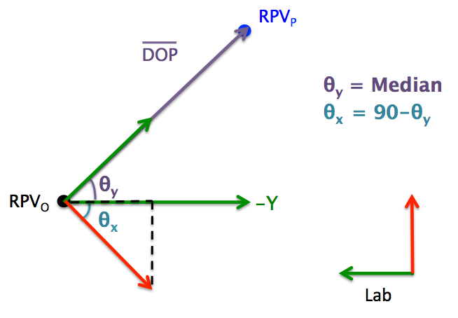 |
Step 2: Define the Virtual Lab
- Create landmark to define the orientation of the virtual lab (Dir_Prog_X)
- Offset in the X: - 0.1 * SIN ( ( 90 - Theta Y ) * pi()/180 )
- Offset in the Y: - 0.1* COS ( ( 90 - Theta Y ) * pi()/180 )
- Offset in the Z: 0
- Create a virtual lab and use the Dir_Prog_X landmark instead of Lab_Other
Step 3: Define the trunk angle relative to the virtual lab
Using Model Compute Model Based Data, calculate the Joint_Angle between the Trunk and Virtual Lab segments.
Method 3
An example script that demonstrates this method can be found here.
Please review the power point slides for a more detailed explanation.
Step 1: Direction of Progression
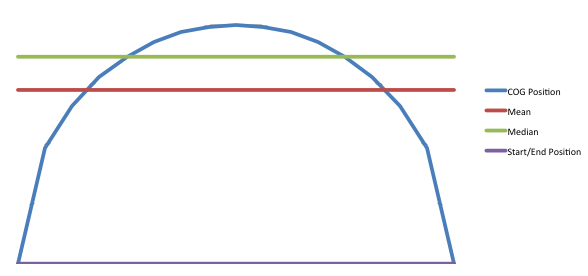
- Find the location of the model's center of mass at the beginning of the trial
- Find the location of the model's center of mass at the end of the trial
- Find the difference between the two locations
- Create the unit vector of the difference
- This result is a metric so this value can be used to define the direction of progression (see here for more information)
- There should be no progression in the vertical direction so set Z=0
Step 2: Define the Virtual Lab
The joint angles will be solved for manually in Step 3, so it is unnecessary to create a virtual lab for this method.
Step 3: Define the trunk angle relative to the virtual lab
- Define rotation from Lab to VLab
- Z component is perpendicular to the ground
- Y component is the direction of progression
- X component is Y cross Z
- Define rotation from Lab to Trunk
- Using Compute Model Based Data command select the Joint_Rotation function and resolve the Thorax/Ab rotation in the Lab coordinate system
- Solve for the rotation between VLab and the trunk segment
- Solve for the joint angles:
- Solve for Theta X
- Solve for Theta Y
- Solve for Theta Z
Method 4
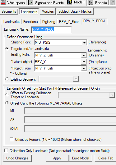
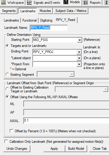
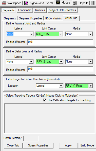
This method creates a Virtual Lab segment that follows the general orientation of the Pelvis (or any segment) but keeps the transverse plane parallel to the lab floor. In other word, this method constrains the Virtual Lab to only rotations around the vertical axis based on the Pelvis segment. This method thus allows to compute variables using the instant direction of progression.
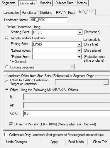
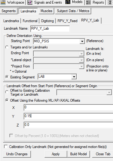
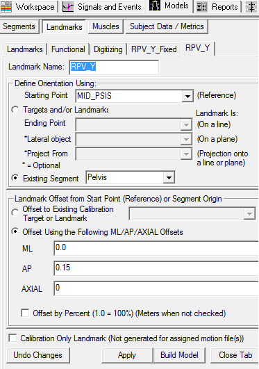
Create Landmarks
Create Virtual Lab Segment
To create the Virtual Laboratory segment, switch to the Segment Tab in model builder mode.
| 1. Create the Virtual Lab Segment: 1. In the Segment Name combo box type Virtual Lab 2. Check the Kinematic Only Check Box 3. Select the Create button | 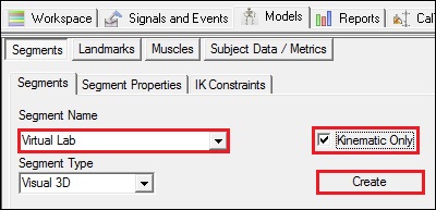 |
